 |
Standard S-7 Clearances and the NMRA Gage by Roger P. Hensley |

During my work with the Standards and RP pages of the NMRA website, I have
answered a number of questions over the past five years or so. Lately, the
questions have concerned the NMRA Mark III and Mark IV Gage and the
clearances represented by it, enough questions that I felt an explanation of the
basis for the clearances to be worthwhile.
Q) I bought a MARK IV standards gage a while back and I know what some of the things on it are used for, such as wheels and track. When I'm at your website and look at a picture of the same gage, there is all kinds of letters on it pointing to different things on the gage. What do all of those letters point to? Can you tell me all of things the things this handy little device measures.
A) Ok, you know about the wheels and track, but if you noticed, the RP-2 page said:
  The Type I GAGE also checks the following:
  Dimensions A, B, C, D, E, F, G, H, and P			STANDARD S-7
and then had a link to STANDARD S-7. If you were to look at STANDARD S-7, you would find that it is clearances for cars and locos. The silhouette of the gage actually checks for clearances of structures, bridges, tunnels and platforms based on the AAR (Association of American Railroads) Plate A, B & C clearances. The railroads need to know how much space is available for cars of specific height and width and they have diagrams of dimensions that they refer to as Plates. My reproduction of the 1953 ORER, Official Railway Equipment Register (available from the NMRA), has a Plate B diagram on page 767. This clearly shows the clearance dimensions in feet and inches, something that we can't do since we are working with multiple scales. Instead, we simply call it clearance and the A,B,C,D,E,F,G,H & P are the chart code for the dimensions represented in the area of the NMRA Gage or the silhouette in Standard S-7. If it were for only one scale, there would be no letters just measurements. If you build to this guide, you will have proper clearance for your cars UNLESS you are very modern and need greater than Plate F clearance for your doublestacks and auto carriers.
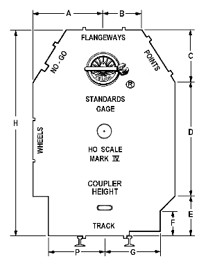
The A, B, C, etc. refer to specific dimensions for structure clearance. For example H is height. In HO, H equals 3 inches from rail head to the top of the structure clearance dimension or about 22 HO feet. A is the distance from the centerline of the track to the outmost clearance for the car and works out to about 15 HO feet across the Right of Way. G (and P) is the distance from the centerline to the clearance for the trucks and undercarriage with F showing how high that clearance goes before is begins to open up. P actually represents the area in which a platform should be constructed and how close it can come to the lower portion of the car. D and E together represent the height of the car before the structure can begin to close on it.
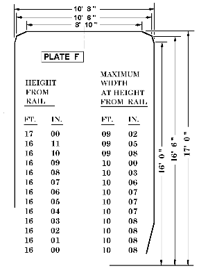
Now, and this is important, I told you that this was for Plates A, B and C. The AAR goes up through Plate F (and now Plate H, I understand) and the silhouette widens at the top, unlike the NMRA Gage. The hi-cube boxcars that you see on the rails that have the white section at the top end of the car are "Exceeds Plate F" or "Excess Height" cars. Doublestacks are even higher.
With the Mark III and Mark IV gage, you can check all of these clearance dimensions for your older equipment and when you understand what the Gage and dimensions represent, you can then calculate the height that you would need for modern cars. A scale rule is almost essential for this as it can make measuring much easier. If you use the 3 inch clearance (22 HO feet), you are good for Plate F as long as you keep the top square as when going under a bridge or overpass.
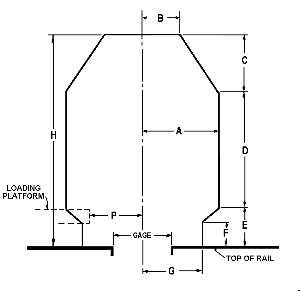
I said that our clearances are based on the AAR Plate diagrams. What are they and how can we use them to work out clearances for doublestacks and tri-level auto carriers? When we look at the dimensions that are the same through Plate F, you find that the lower measurements and the width are almost a constant for Plate B through Plate F. The AAR car width is 10' 8" with an additional 2" allowed for grab irons and latches. The width of the car doesn't change with the larger Plate clearances. Our corresponding dimension taken from S-7 and the Mark IV NMRA Gage is right at 15 HO feet. That's 2 times the A dimension.
This isn't rocket science and you will note that I am not splitting hairs with these dimensions. A hair less than 15 HO feet is 15 HO feet for all practical purposes. Our clearances are wider than the prototype to allow for differences in model building, trucks, wheels and even car width, track curvature and tunnel building. Before we go further, you should realize that the dimension P as drawn on the S-7 clearance diagram is a little misleading. P is the same as G. The drawing is trying to illustrate that a loading platform can come as high as dimension E, but should be located in that area and should follow the slope depending upon the height. Passenger car platforms are generally lower, but that is another story.
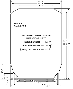
AAR Plate B diagram
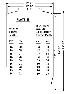
The diagram of Plate B slows the slopes of the lower clearances and shows full width reached at 3' 4" above the top of the railhead. The width is 10' 8" at the widest part with an overall height of 15' 1" and a span of 7' across the top before the silhouette begins to fall off. It was designed for cars up to an inside length of 50' 6", coupled length 54' 8.5" and a truck centerline to centerline of 41' 3". Not exactly modern doublestack dimensions. But note that the width does not change as the height grows. The means that many of the dimensions on the Mark IV NMRA Gage are still good today and will continue to be for a long time to come. However, this is where we need to look at the larger Plate diagrams and do some calculating. Plate E carries a height of 15' 8" with a narrow allowance at the top and Plate F jumps to 17' 0" and a nearly flat top. For even Plate F clearances, you may already be having some problems with tunnels and bridges. I used the 3 inch measurement when I put in my bridges and I can clear a "Exceeds Plate F" Hi-cube boxcar with HO inches to spare.
But what do we do with a doublestack? How much room do we need? If the silhouette of the 'Standards Gage' will not work for doublestacks and tri-level auto carriers, what do we do? Understanding the AAR Plates and prototype measurements can provide you with the answer. The doublestack clearance on the prototype is 20' 5" (ATSF and CR) and 20' 8" (NS minimum clearance). Either of these dimensions should handle any correctly loaded doublestack car. A typical doublestack loaded with two empty 9' 6 1/2" containers will come out at about 20' 2", just under the 20' 5" of most railroads. NS prefers more clearance and you can see why with the potential height of unloaded containers. Loaded, the same car should be slightly under 20'. That's for the prototype. How about a tri-level auto carrier? Well, that will probably come in at about 19' in height, lower than the doublestack, but longer by 15 to 20 feet.
What does this mean to you? If your car doesn't ride high on its trucks and the containers are the correct height, you could clear the 22 HO feet as long at the silhouette is wide at the top, but don't count on it! Remember that we allow extra space for our models. In fact, we said that we allowed a 22 HO foot height for Plate C. I would suggest a safety margin for modern cars would be at about 25 1/2 HO feet or 3.5 inches (actual) with a wide top flat top of nearly the full width of the NMRA Gage or 13 to 15 HO scale feet. This can have a dramatic effect on your tunnel portals if your existing railroad decides to put on a doublestack train. Modern cars are no wider than their 1960 and 70 counterparts, 10 foot 8 inches or less, but they may be longer and higher. That means that as long as you enter your portal straight and stay straight for nearly a car length, your side to side clearances are still good. Height? Ah, well, that's the part that can get nasty.
I can tell you that 3 inches in HO isn't enough clearance even though it is taller than 20' 5". The reason is that we are not prototypical. Our clearances are greater than the prototype. They have to be to compensate for wheels and car construction that may be larger than perfect scale dimensions. We may have to do exactly like the prototype has done when they removed a second track into tunnels to get clearance at the top by moving the remaining rail line into the center. In other words they have used a double portal instead of a single in order to gain height. What can you do if you are installing a tunnel portal and it isn't going to give you the upper clearance that you need? Well, we are modelers. If your portal doesn't have the clearance, you mount it by adding extra material to the bottom when you install it. Make a fake concrete or stone base to get your height. If that doesn't seem to be an option, lower the track. Lowering the track may have to be done to clear existing bridges as well. Width dimensions only comes into play when you must turn as soon as you enter.
Remember, that the clearances of the NMRA S-7 STANDARD and the AAR Plate dimensions are based on tangent (straight track). The sharper the curve, the more side to side allowance you will need to make. Will there be a new NMRA Gage? Of course. Will there be revisions to S-7? Yes. But in the meantime, I'm not going to throw out my old Mark III HO Gage as long as I can use it knowing the new upper prototype dimensions that I need to make allowances for if I modernize my freight traffic. Everything that I've said here concerning S-7 dimensions can apply to any scale. Just substitute the correct values for your scale where I reference HO.
I received an e-mail from one of those who asked about the NMRA Gage and S-7 clearances. He said,
- "By the way, since my last email to you, while looking through a steam era book, I came across a photo of the entrance to a concrete-lined tunnel. The upper half of the portal was a dead-ringer for the upper portion of the Gage silhouette - AHA!!"
Roger
Note: The clearances that were used for S-7 were developed by Meredith Smith, the NMRA Engineering Manager, from the American Railway Engineering Association (AREA) standards. They were first published in the NMRA Bulletin in March 1940. The AREA is a counterpart to the AAR. AAR deals with cars, trucks, and wheels. The AREA deals with bridges, tunnels, and structures.
and was Standards/RP Web Page Manager for the NMRA website.
You can learn more about clearance dimensions and how the NMRA Gages are intended to check clearances, trackwork and wheels by visiting the NMRA Standards and Recommended Practices web pages at: www.nmra.org/standards.
"NMRA", "National Model Railroad Association" and "National Train Show®"
are registered trademarks of the National Model Railroad Association, Inc.
This page is written and maintained by:Tim Klevar, tjklevar@comcast.net
This page is hosted by: Eric Schnoebelen of cirr.com